Spire: Intrusion-Tolerant SCADA for the Power Grid
Deployment Overview
Spire consists of three components: Spire, Confidential Spire and Spire for the Substation. Below is detailed documentation of base Spire.
The documentation for building and running Confidential Spire is here.
The documentation for building and running Spire for the Substation is here
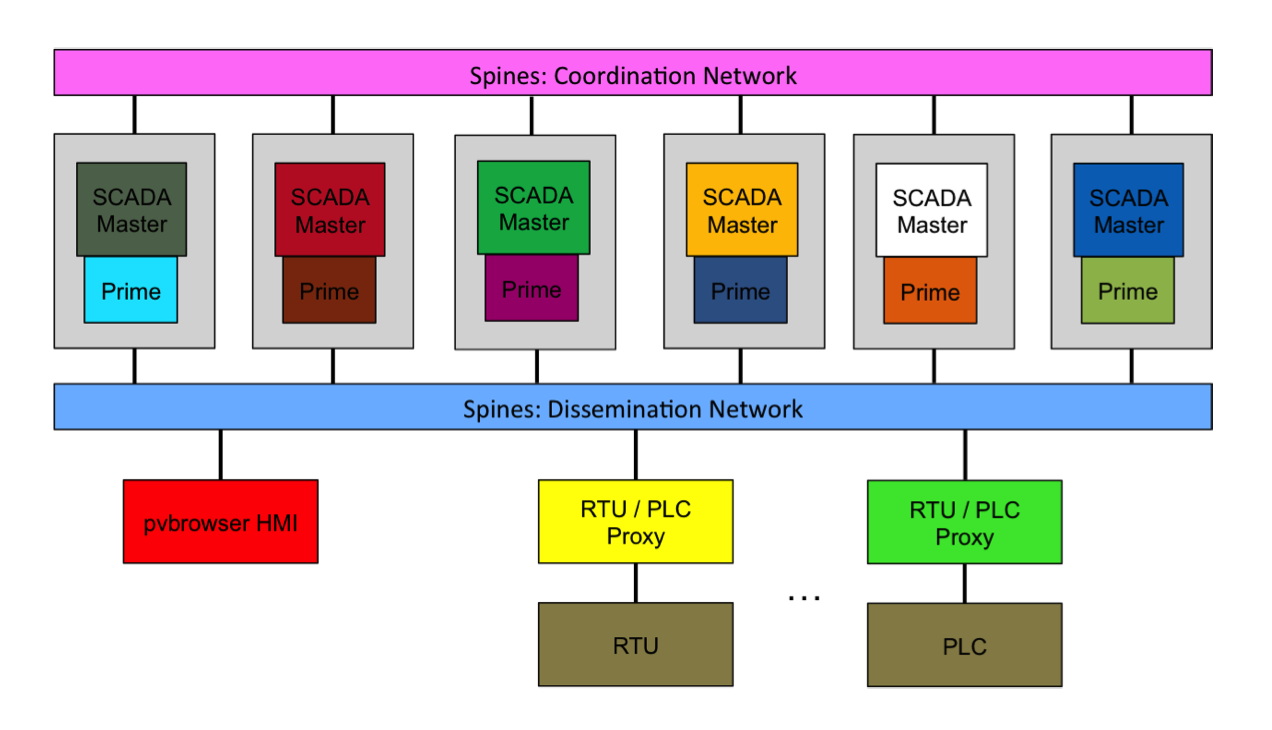
A Spire deployment includes: SCADA Master replicas, Prime daemons, Spines daemons, PLC/RTU proxies, real or emulated PLCs and/or RTUs, and HMIs. These components can be distributed over multiple sites connected by a wide-area network, over multiple logical sites within a local-area network (with or without emulated wide-area latency) or as a single site in a local-area network.
We typically deploy Spire with SCADA Master replicas distributed across several sites. For each SCADA master replica, we also deploy a Prime daemon that the SCADA master connects to. Each SCADA master is located on the same machine as its Prime daemon and connects to it via IPC.
Communication in the system occurs over two Spines overlay networks: an external network and an internal network. The external network is used for communication between the SCADA Master replicas and the PLC/RTU proxies and the HMIs. The internal network is used for communication among the SCADA Master replicas (and their Prime daemons). External and internal Spines daemons can be deployed on the same machines but use different ports.
We distinguish between two types of sites that can contain SCADA Master replicas: control centers and data centers. This is because power grid control centers with full capabilities for controlling PLCs and RTUs are generally expensive, and utility companies are unlikely to deploy more than two. To support the desired resilience with only two control centers, we allow additional sites to be added as data-center sites that do not control PLCs or RTUs.
In each site that contains SCADA Master replicas (including both control centers and data centers), we typically deploy one Spines daemon that participates in the internal network to connect the replicas in that site to the other sites. In each control-center site, we additionally deploy a Spines daemon that participates in the external network to connect the replicas in that site to the proxies and HMIs.
In the normal flow of the system, there are two main types of events: HMI commands and PLC/RTU updates. When an HMI command is initiated (e.g. a user clicks a button to make a change), the command is sent to the control-center SCADA Master replicas over the external Spines network. The SCADA Master replicas pass the command to their Prime daemons, which disseminate it to the data-center Prime daemons and execute a Byzantine-fault-tolerant agreement protocol to agree on the command. When the Prime daemons have agreed on the command, they pass it back to their SCADA Masters. The SCADA Masters then execute a threshold signing procedure on the command (so that the PLC/RTU proxy can verify that a sufficient number of replicas agreed on the command by verifying a single signature on a single message). The control-center SCADA Masters then send the threshold-signed command to the PLC/RTU proxies. The proxies verify that the command has a valid threshold signature and then pass it on to the PLC(s) or RTU(s).
PLCs and RTUs are periodically polled by their proxies. When a proxy has new PLC/RTU data, it sends the data to the control-center SCADA Master replicas over the external Spines network to be agreed upon and sent to the HMI. The HMI verifies the threshold signature on the update and updates its display.
Configuration
There are several configuration files relevant to the Spire system:
- Main Spire configuration: common/def.h
- See comments within the file for configuration parameters and descriptions.
- PLC/RTU configuration: config/config.json
- This file specifies the PLC/RTU Proxies and the PLCs and RTUs in the system. At the top, the total number of proxies in the SCADA system is specified. Each individual PLC/RTU proxy then has its own configuration settings, including a unique ID (starting at 0) and the protocols of the PLCs/RTUs this proxy will need to use (i.e., Modbus and/or DNP3). Then, the specification of the individual PLCs and RTUs under the control of each Proxy is listed. These settings include which scenario (JHU, PNNL, EMS) that device belongs to and then Modbus-specific and DNP3-specific settings, such as the IP address and Port on which to connect with and the various field types and locations of the data stored in the PLC/RTU that is collected from equipment.
- NOTE: the Modbus and DNP3 configuration settings for the PLCs/RTUs must match the specification of the real (or emulated) PLC/RTU devices in order to properly connect with, monitor, and control those devices.
- Prime configuration files (prime/src/def.h, prime/bin/address.config, prime/bin/spines_address.config) -- see Prime documentation for details.
- Spines configuration (spines/daemon/spines.conf) -- see Spines documentation for details. Note that internal and external Spines networks may use different configuration files.
Building
Installation Prerequisites
- General Prerequisites
- OpenSSL development package (e.g.
yum install
            openssl-devel
, orapt-get install libssl-dev)
- OpenSSL development package (e.g.
- Spines Prerequisites
- Lex and Yacc (e.g.
yum install flex byacc, orapt-get install flex byacc)
- Lex and Yacc (e.g.
- HMI Prerequisites
- QT development package and webkit (e.g.
yum install qt-devel epel-release qtwebkit-devel,apt-get install qt-sdk) - pvbrowser:
pvbrowser is packaged with Spire 1.1, located in the pvb directory.
To build pvbrowser (from the top-level Spire directory):
make libs
- QT development package and webkit (e.g.
- DNP3 Support Prerequisites
- cmake (e.g.
yum install cmake, orapt-get install cmake) - gcc and g++ 4.9 or higher
- Note that if your gcc/g++ >= 4.9 is not the default system gcc/g++, you
will need to modify:
- The Makefile in the dnp3 directory (set CXX and CXXLIB variables to point to your installation of g++ 4.9 or higher)
- The build.sh script in opendnp/opendnp3_build (set C_LOC and CXX_LOC to point to your installation of gcc and g++ 4.9 or higher, and use the alternative cmake command that specifies these locations)
- The OpenPLC build.sh and core/core-builders/build_normal.sh scripts (set CXX_LOC variable to point to your g++ >= 4.9)
- Opendnp3: Opendnp3
is packaged with Spire 1.1 in the opendnp3/opendnp3 directory. To build
(from top-level Spire directory):
make libswill build this module also.
- cmake (e.g.
- OpenPLC (optional, for PLC emulation/creation)
- A version of
OpenPLC with added DNP3 support is packaged with Spire 1.1 in the
OpenPLC_v2 directory. To build (from top-level Spire directory):
make libswill build this module also. Select "1) Blank" when prompted to build emulated PLCs for Linux.
* Note that the version of OpenPLC above with added DNP3 support will eventually be merged with the main OpenPLC branch.
- A version of
OpenPLC with added DNP3 support is packaged with Spire 1.1 in the
OpenPLC_v2 directory. To build (from top-level Spire directory):
Spire Build Process
Note: Because the base Spire and Confidential Spire share certain configuration files and executables with compiled-in configuration parameters, we do not currently support running both versions at the same time. To switch from a Confidential Spire configuration to a base Spire configuration, first run `make clean` from the top-level Spire directory, and then follow the instructions below to build Spire.
- Build Spines, pvbrowser, and OpenPLC: (from top-level Spire directory):
make libs
- Build Spire (from top-level Spire directory):
make
Generating Keys
All system entities use RSA keys to authenticate messages, so keys must be generated before the system can run.
Spines
To generate keys:
cd spines/daemon; ./gen_keys
This creates 10 public-private key pairs in spines/daemon/keys (if you have more than 10 Spines daemons, you can modify the for loop in the script to create more keys)
Each Spines daemon should have access to its own private key (i.e. the Spines daemon listed as host 1 in the spines.conf file should have the key private1.pem) and the public keys of all the Spines daemons.
Prime
To generate keys:
cd prime/bin; ./gen_keys
This creates the following in prime/bin/keys:
NUM_SERVERSserver public-private key pairs (with public keys public_01.key, public_02.key, ... and private keys private_01.key, private_02.key, ...)NUM_CLIENTS(default 150) client public-private key pairs (e.g. public_client_01.key, private_client_01.key)- 1 public key used by Prime daemons to authenticate threshold-signed messages used in the Prime protocol (pubkey_1.pem)
NUM_SERVERSthreshold crypto shares used to generate threshold signatures in the Prime protocol (share0_1.pem, share1_1.pem, ...)
Each Prime daemon should have access to its own private key and threshold crypto share (i.e. replica 1 should have keys private_01.key and share0_1.pem) and all public keys.
Note that Prime's gen_keys program currently generates SCADA Master threshold crypto shares as well (see below).
Spire
To generate keys:
cd scada_master; ./gen_keys
Since we consider a SCADA Master + its co-located Prime daemon one "replica", each SCADA Master uses the same public-private key pair as its Prime daemon (e.g. SCADA Master 1 uses the key pair prime/bin/keys/public_01.key, prime/bin/keys/private_01.key).
PLC/RTU proxies and HMIs act as clients of Prime and use Prime client keys.
- Proxies calculate their Prime client ID as
NUM_SM +
                1 + id
, whereidis the ID of the proxy and ranges from 0 toNUM_RTU - 1(so in a system with 4 replicas, proxy 0 should have the key pair public_client_05.key, private_client_05.key, proxy 1 should have public_client_06.key, private_client_06.key, etc.).
* Note that benchmark clients (see "Running" section) use the same keys as a proxy with the same ID would. - HMIs calculate their Prime client ID as
NUM_SM + 1 +
                MAX_EMU_RTU + id
, whereidis 1 for the jhu_hmi, 2 for the pnnl_hmi/heco_3breaker/heco_5breaker/heco_timing HMIs, and 3 for the ems_hmi.MAX_EMU_RTUis 100 by default. In a system with 4 replicas, the jhu_hmi would have public_client_105.key and private_client_105.key, the pnnl_hmi/heco_hmi would have public_client_106.key and private_client_106.key, and the ems_hmi would have public_client_107.key and private_client_107.key.
SCADA Master replicas execute a separate threshold-signing protocol outside of Prime to create threshold signatures that PLC/RTU proxies and HMIs can use to verify that the updates/commands they receive were agreed upon by enough replicas. For this, the SCADA Masters use their own set of threshold crypto shares.
- These keys are generated by the scada_master gen_keys
script. After scada_master/gen_keys has been run, these key
shares will be located in scada_master/sm_keys. The
scada_master/sm_keys directory includes:
- 1 public key used by PLC/RTU proxies and HMIs to verify threshold signatures (pubkey_1.pem)
NUM_SERVERSthreshold crypto shares (e.g. share0_1.pem, share1_1.pem, ...)
Each SCADA master should have access to its own public-private key pair, its own threshold crypto share, all SCADA master public keys, the threshold crypto public key, and all client public keys
Each PLC/RTU proxy and HMI should have access to its own public-private key pair and all SCADA master and client public keys, and the threshold crypto public key.
Running
The following instructions describe how to run all the components of
the Spire system. Note that command line parameters in
ALL_CAPS should match the corresponding parameters in
common/def.h
-
Run all Spines daemons (for both the internal and external Spines networks)
- 1 internal Spines daemon per site containing SCADA master replicas
- 1 external Spines daemon per control-center site
- 1 external Spines daemon for PLC/RTU proxies to connect to
- 1 external Spines daemon for HMI to connect to (can be the same as the one the proxies connect to)
To run (internal Spines network):
cd spines/daemon; ./spines -p SPINES_INT_PORT -c spines_int.conf
To run (external Spines network):
cd spines/daemon; ./spines -p SPINES_EXT_PORT -c spines_ext.conf
These commands assume that the internal and external spines configuration files are located at spines/daemon/spines_int.conf and spines/daemon/spines_ext.conf, respectively.
-
Run all SCADA masters
To run (control center):
cd scada_master; ./scada_master id spines_int_ip:SPINES_INT_PORT spines_ext_ip:SPINES_EXT_PORT
To run (data center):
cd scada_master; ./scada_master id spines_int_ip:SPINES_INT_PORT
The spines_int_ip and spines_ext_ip should be the IP addresses of the internal and external Spines daemons this replica connects to. They should match addresses specified in
SPINES_INT_SITE_ADDRSandSPINES_EXT_SITE_ADDRSin common/def.h.The
idshould be the ID of this replica, where IDs range from 1 toNUM_SM. The code assumes replicas are striped across sites; for example, for 12 replicas and 4 sites (of which 2 sites are control centers) we have:NUM_SM= 12,NUM_SITES= 4,NUM_CC= 2- Site 1 (control center): Replicas 1, 5, 9
- Site 2 (control center): Replicas 2, 6, 10
- Site 3 (data center): Replicas 3, 7, 11
- Site 4 (data center): Replicas 4, 8, 12
-
Run all Prime daemons
To run:
cd prime/bin; ./prime -i id
The
idof a Prime daemon must match theidof the SCADA Master that connects to it (and is running on the same machine as it).Prime uses its configuration files to find the location of the internal Spines daemon to connect to (see Prime documentation).
-
Run PLC/RTU proxies
To run:
cd proxy; ./proxy id SPINES_RTU_ADDR:SPINES_EXT_PORT 1
The id should be the ID of this proxy, where IDs range from 0 to (NUM_RTU - 1). This ID is also used to look up information about the PLC/RTU in the config.json file.
-
Run the HMIs
To run (jhu):
cd jhu_hmi; ./jhu_hmi SPINES_HMI_ADDR:SPINES_EXT_PORT -port=pv_port_jhu
To run (pnnl):
cd pnnl_hmi; ./pnnl_hmi SPINES_HMI_ADDR:SPINES_EXT_PORT -port=pv_port_pnnl
To run (ems):
cd ems_hmi; ./ems_hmi SPINES_HMI_ADDR:SPINES_EXT_PORT -port=pv_port_ems
pv_port_*is the port on which the HMI will accept pvbrowser connections to interface with the GUI that reflects the current power grid state and allows a human operator to enter commands.To connect GUI: Run pvbrowser application (located in main pvb installation folder). In the browser's address bar, give the IP address of the HMI and the
pv_port(e.g. 192.168.101.108:5050). -
(Optional) Run OpenPLC PLCs
cd plcs/jhu0; sudo ./openplc -m 503 -d 20001
...
cd plcs/jhu9; sudo ./openplc -m 512 -d 20010
cd plcs/pnnl_plc; sudo ./openplc -m 502 -d 20000
cd plcs/ems0; sudo ./openplc -m 513 -d 20011
cd plcs/ems1; sudo ./openplc -m 514 -d 20012
cd plcs/ems2; sudo ./openplc -m 515 -d 20013
cd plcs/ems_hydro; sudo ./openplc -m 516 -d 20014
cd plcs/ems_solar; sudo ./openplc -m 517 -d 20015
cd plcs/ems_wind; sudo ./openplc -m 518 -d 20016
The
-moption is the Modbus port, and the-doption is the DNP3 port. These should match what is specified in the config.json file for each PLC. See the OpenPLC documentation for instructions on creating your own PLCs. -
(Optional) Run Benchmark Clients
We also provide a benchmark client that can be used to test and measure the core of the system without running an HMI, PLC/RTU proxies, or PLCs/RTUs. The benchmark client submits updates to the system. The SCADA Masters agree on each of these updates just like they would for a normal PLC/RTU update and then send a response back to the benchmark client. The benchmark client calculates and prints the latency for processing each update (measured from the time it creates the update to the time it receives the corresponding response).
To run:
cd benchmark; ./benchmark id SPINES_RTU_ADDR:SPINES_EXT_PORT poll_frequency(usec) num_polls
The benchmark client will send an update every "poll_frequency" microseconds and will exit after completing "num_polls" updates. Benchmark client ids range from 0 to (NUM_RTU - 1).